Saturday, February 27, 2010
Shakedown
Since the last post, the clutch has been replaced. The kit included a heavy-duty clutch, pressure plate and release bearing (from Sunbury Brakes in Australia, here is the kit).
Since the kit did not include a pilot bearing, I had to find one on my own. It turns out that the pilot bearing from the stock gasoline Trooper engine is the same, so I used that application to order a new one from NAPA - works without issue. The transmission input shaft, release lever, release bearing, bearing retainer clip, etc. are all the same between the gas and diesel transmissions. I ordered a rear main seal from an Isuzu industrial dealer, giving them the engine model as the application.
Two problems have grounded the Trooper since the clutch was replaced. The first was a fuel starvation issue, which I traced to the sock filter I had added to the bottom of the fuel pickup tube I fabricated in the fuel tank. I had to remove the tank, pull the pickup assembly and remove the filter, which was completely stopped up. I think the biodiesel melted it a bit, as it seems to be made of nylon. I just left the pickup tube bare - I have a prefilter installed before the main filter/separator assembly, and any junk that comes up from the tank will be caught in the (very cheap and easily accessible) prefilter. The sock filter was meant to protect an in-tank electric fuel pump from debris; not necessary in this application. I also took the time to repair the wiring for the fuel gauge, and I now know how much fuel I have in the tank.
The second problem was a very sudden loss of heat on the freeway. I exited and pulled over, and quickly confirmed my suspicion that I had lost all coolant. After towing the truck home and inspecting the cooling system, I found that an expansion plug (also known as a freeze plug or frost plug) had fallen out of the block.
This was the same plug that had popped partially out a couple of winters ago when I had inadvertently left some water in the block (thought it was drained totally; I now will always leave antifreeze in the system, no matter the circumstances). I tapped it back in at that time, but I guess it was crooked or damaged.
Luckily, this particular plug is the easiest one to access on the entire block - between the starter and injection pump on the driver's (or left) side of the engine. Determining what size plug to get was the most time-consuming part of replacing it - while the plug is the most accessible, access isn't all that great, and I couldn't get any sort of measuring device close enough to get a reading. I tried to order the plugs from the stock gas engine block, but they were too small. I finally found a website with parts diagrams of the block (see here) and was able to determine that the large plugs are 45mm in diameter. Of course, no local parts houses had a plug this size.
Mr. Lemond, Isuzu parts guru, sent me a stock Trooper diesel plug (C223 engine from '86-'87 also has 45mm plugs) as well as a block heater made for this size opening. I was able to install the block heater by carefully choosing the angle of installation (the plug is behind the oil pressure sender and the fit is tight - the electrical connector has to be at about 1 or 2 o'clock to clear it). I also had to remove the oil pressure sender in order to access the area, and tapped the block heater in by using long socket extensions inserted through the fender skirts in the driver's side wheel well. Once it was tapped in (to seat the o-ring), I tightened it from the same wheel well location.
Installing the oil pressure sender was tricky. I had to trim a small amount of rubber off the end of the heater's electrical cord to gain some additional clearance. I then inserted the cord, and spent a great deal of time trying to get the sender's threads started, as it was rubbing on the electrical cord connector. Once it was started, it went in smoothly, and there may even be a hair's breadth clearance between the cord and the body of the sender.
On balance, I am glad the plug fell out, as it gave me an excuse to install a block heater, something I have been meaning to do for some time. I am glad there was no damage to the engine when the coolant was lost. I've driven it a bit since then and all seems well - must be the cool-running diesel and overall ruggedness of the 4JB1-T that saved me.
Tuesday, September 08, 2009
On the road
After the hood was completed (except for the awful rust repair at the front edge - I will be smoothing this out soon), I plated and insured the truck. I also adjusted the front suspension, as it was bottomed out from the added weight of the diesel engine. Next was a trip to the exhaust shop, and the trooper now sports a full turbo-back 2.25" exhaust system, which sounds great (I will try to get some photos of this later). Finally, I spent a good deal of time cleaning the carpets and the interior generally, as it was pretty filthy from farm use and neglect. It's quite nice now.
I also realized the clutch is junk, and am wishing I had changed it when I had everything apart. A new clutch kit arrived from Australia last week, so I am now going to remove the transmission to install it, along with a new rear main seal. After that, it's down to some wiring cleanup and tightening the drive belts for immediate tasks. There will be some more rust repair a bit later (rear doors), but that can wait a while.
I can say it's a lot of fun to drive - good response, lots of torque (when I can get it to the ground). More later once the new clutch is in.
Intercooler hood scoop installation, pt. 4


Intercooler hood scoop installation, pt. 3


Intercooler hood scoop installation, pt. 2


Intercooler hood scoop installation
Over two years and no updates - the project continues, despite some setbacks to the schedule.
An attentive reader might recall a post from the distant past detailing the intercooler hood scoop I imported from Australia, which arrived with the surrounding hood attached (the entire assembly was cut free from the hood with a saw). I have finally gotten around to installing the scoop, details below.
The hood structural supports are different on a hood with an intercooler scoop; instead of meeting at a center crossing point as they do in a normal hood, the main supports are cut and two new members are fitted which avoid the hole punched for the intercooler. Additionally, there is a steel ring which fits into the cutout, providing the bolt-on mounting for the rubber sealing gasket. The scoop itself is fiberglass and attaches to the hood with studs from the underside. The scoop is centered on the hood, while the hole beneath is offset to the passenger side to match the location of the intercooler.
To install the scoop onto my hood, I drilled out the spot welds securing the two structural members, their support gusset plates, and the sealing gasket attachment ring on the imported hood section (after disassembling everything and removing the scoop and gasket).
I then removed the rearmost structural member from the hood section by cutting it away near its attachment at the panel's outer skin. What was left was the skin of the hood section, which I used as an overlay on top of my hood to scribe the locations for the bolt holes and intercooler cutout. I also used the structural members I removed to scribe the cuts to the members on the underside of my hood, as well as to scribe locations for holes to be cut in the rearmost structural member to allow access to the studs which secure the scoop.
With everything marked, I cut the structure away on my hood using a cutoff wheel. I then marked the location of the hole for the intercooler with tape and cut it with the wheel, finishing the radiused corners with a die grinder. I also used a hole saw and die grinder to cut holes for the scoop mounting studs in the rear structural member (nearest the cowl).
The replacement structural members were then attached to the hood using panel adhesive and tack welds (to mimic the spot welds; technically these are probably rosette welds). Using panel adhesive, available at paint/body suppliers, is important so that the skin of the hood stays tied to the structure. This is how the factory constructed the hood, so I thought I should imitate the procedure.
Following that, the sealing gasket mounting ring was tacked to the upper side of the hood and the scoop mounting holes were drilled and adjusted with a die grinder to fit. I also did a quick job of painting the welded areas and cleaning things up a bit.
The scoop was then bolted into place with some silicone sealant instead of the foam gasket I found underneath it on the imported hood section, and the hood was reinstalled.
I am happy with the result, although my measurements were slightly off to one side and it's not perfectly centered. Someone else might not notice unless it was pointed out to them, though, as it's really close.


Thursday, June 28, 2007
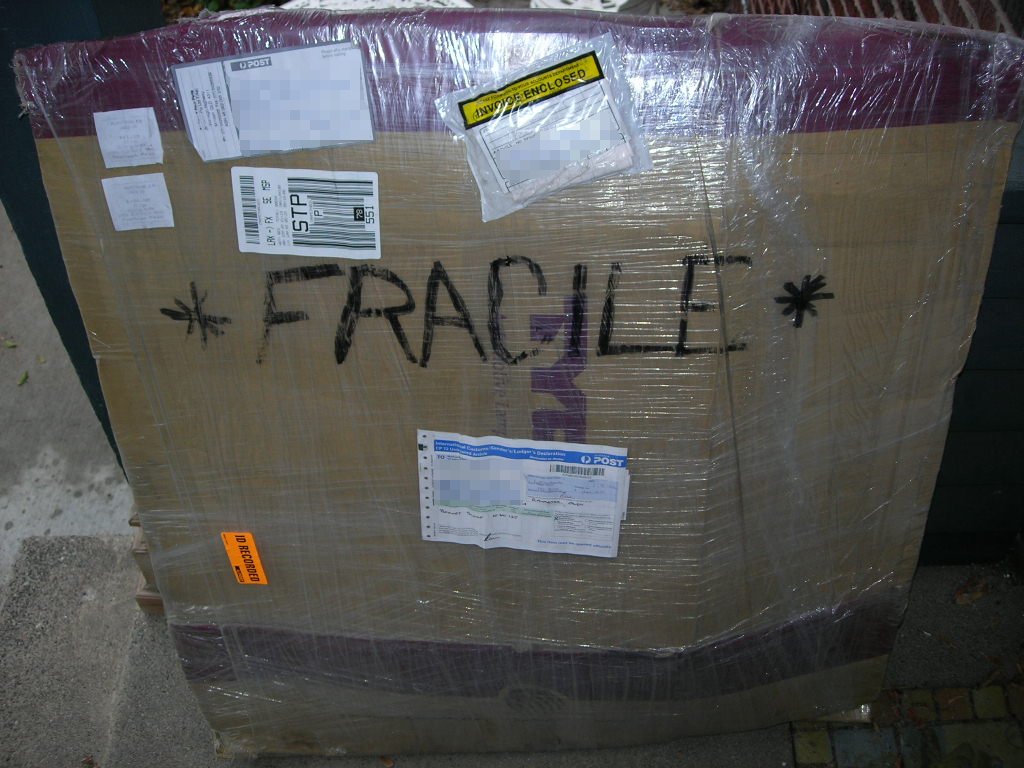
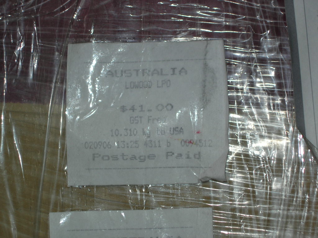
Fuel tank installation, pt. 3


 A few more shots of the tank installation.
Fuel tank installation, pt. 2

The solution to the filler neck dilemma was to fabricate a tube to connect the new tank to the (shortened) original rubber fuel filler hose.
I began by ordering a piece of 1-3/4" I.D. mandrel-bent mild steel exhaust, something called a J-bend. This piece of tubing is used by custom header and exhaust fabricators and features a 180-degree bend and two legs of different lengths.
Next, I took a number of measurements of both tanks to determine the location of the filler necks on each. I used one of the mounting bolt holes on the tank flange as a reference point, as these holes were the same on both tanks. Using a straightedge and a long screwdriver (through the bolt hole, to obtain a reference line) I was able to measure the location of the necks fairly accurately.
These measurements were then used to generate a CAD drawing of the two tank necks. Additionally, I drew the J-bend and the rubber filler hose. All of this information was used to determine the best way to use the J-bend to connect the existing filler hose to the new tank. The CAD drawings were then printed and used as full-scale patterns to cut the J-bend, weld the pieces together and to cut the filler hose.
The filler hose was cut just after the first right angle bend (just as it begins to travel sideways after dropping from the gas cap area). The J-bend was cut into sections and tack-welded into an S-shape for initial fitting. After determining that the fit between the frame and bed support channel was too tight, I flattened the tube a bit in the middle in order to get it to fit. I also purchased a Gates universal 45-degree bent fuel filler hose, as I needed the 45* bend to connect the tube to the new tank's neck, which is at a more upward angle than the old neck.
My clumsy welding caused a burn-through during finish welding of the tube, so I coated the entire junction with J-B Weld to seal it. The final fit is extremely tight, but it works - leak free, so far.
The other difference was in the location of the overflow pipe. I had to bend it slightly sideways to get it to clear the body bed support channel, then buy a length of 1/2" I.D. fuel hose to connect it to the filler cap (the old one was too short).


Fuel tank installation, pt. 1
The fuel tank I removed from the Trooper had very old gas in it. As a result, semi-solid residue was being drawn into the fuel filter, clogging it. I had tried to clean the tank, but it was obvious that there was a substantial amount of residue in the tank.
My options were to either have the tank professionally cleaned (quoted at $300 and up), keep replacing fuel filters until the problem went away ($25 each) or replace the tank with a clean one ($200). I decided to go with option 3 - that's the cost of 8 clogged filters, something I thought possible based on the condition of the old tank.
The problem: the new tank was not quite the same as the old one. Aftermarket tanks were no longer available from the suppliers I contacted, so I went with an OEM unit. It seems that changes were made at some point, however, as the new tank differed slightly from the old one. The main change was to the fuel filler neck location: the new tank featured a centered neck, while the old tank's neck was located toward the rear and angled back. This difference meant that the old fuel filler hose would not connect to the new tank, leaving me with no way to fill it.


Monday, June 25, 2007
Fuel system


As the 4JB1-T injection pump is on the driver's (in North America, at any rate) side of the engine, the factory gasoline fuel line termination at the passenger's side frame rail near the firewall had to be addressed.
I had initially run rubber hoses from the factory hardlines up and over the firewall, down the fender and to the filter/primer pump assembly. In search of a more permanent solution, I decided to install steel lines in place of the rubber hoses, following the same route.
The new lines are formed from 6' lengths of brake and/or fuel line and are secured along part of their route by the factory clips (one of which used to keep the clutch line in place when it ran across the firewall; the other was empty), one new bracket (connected to the cruise control actuator mounting holes and running up the firewall) and a few rubber line clamps.
The new steel lines connect to the factory fuel supply and return lines at the passenger- side frame rail with short lengths of rubber hose, and to the filter/pump assembly with loops of hose. I am not terribly worried about the proximity to the exhaust where the new lines meet the factory lines; although it is close, I plan on fabricating a heat shield if necessary.
Braking system rebuild


 After hard farm use and two years of sitting outdoors, the brakes on the Trooper were in poor condition - the calipers were seized (along with their mounting bolts), the rotors were rusted, the pad friction material had separated from the steel backplate, and the fluid was completely black.
I repacked the front wheel bearings and locking hubs, replaced the grease seals, had the front rotors machined and installed a new set of calipers and pads.
The rear brakes received similar treatment: new rotors, calipers and pads. I also lubricated the parking brake cables and pivot points, replaced one of the parking brake cables and adjusted the system. Fresh fluid completed the rebuild.
Wednesday, October 04, 2006
Scoop


After many failed attempts, I've finally gotten my hands on a genuine Isuzu intercooler hood scoop. A few private parties fell through (I was trying to get someone from New Zealand or Australia to ship me a scoop) and more than one supplier refused to help.
Only one outfit, All Four X Four Parts in Australia, was willing to sell me the parts. They did a fantastic job, cut the scoop free with part of the hood and all the mounting hardware intact, and even included the sealing gasket. Great guys to deal with. Check them out online.
Now I need to weld it into the hood...
Heater hoses


As delivered, the heater hoses on the diesel engine appeared intact. Closer examination revealed that they were both torn and in need of replacement. Both hoses are shaped units, unavailable in the USA (at least, one cannot walk into a parts supplier and order hoses for this application) and, after my experience trying to find a lower radiator hose, I was in no mood to try and find something that would work from another vehicle.
The solution was to duplicate the more complicated bends in copper plumbing pipe and use standard 5/8" heater hose for the rest. All that was required beyond the copper shown above was a straight length of hose and one 90* bent rubber hose, which should be easy to find in a parts catalog.
The main issue was finding a way to duplicate the bead found on the end of factory steel hose connections, which is present to prevent the hose from popping off. I used a flaring tool to create a single flare in 1/2" copper plumbing pipe (the 5/8" die works perfectly for this, don't ask me why) and then employed a combination of 90* elbow fittings, T-fitings and 5/8" copper repair sleeve to create the tubes shown above. The flared 1/2" pipe fits into the enlarged areas of the elbows and Ts, and those oversized sections are the perfect size for the I.D. of the heater hose.
The T-fittings are present to allow for the future plumbing for the SVO heating tank and possibly a coolant heater for winter starting. They are closed off at this time with plugs (one shown above left) and a short section of hose.
Saturday, July 15, 2006
Coolant leak
 After filling the radiator for the first time a few weeks ago, I immediately noticed a large coolant leak coming from somewhere near the alternator, under the A/C compressor (this was why I filled it with water initially!). I had other things to do and so let it be for a while. I was able to repair it today, or so it seems... it has not yet been pressurized, but it doesn't leak during filling like it used to.
I removed the A/C compressor and was able to spot the leak - coming from the water pipe connection at the block. These types of connections employ a metal pipe with an O-ring around the end, slipped into a machined area of the block (in this case, a bolt-on water neck) and secured with a bolt. I've seen similar designs used by Honda. In any case, this water pipe runs from the block, loops around the alternator and becomes the lower hose connection underneath. It is similar to the water pipe found on the 4-cyl. Isuzu Trooper gas engine in this regard.
I removed the two bolts, one at each end of the pipe, which secure it to the engine. I also removed the alternator heat shield which bolts to the pipe - one of the mounting tabs is visible in the photo. I could then pull the pipe out of the water neck. The alternator has to be removed to get the pipe out completely, but I was able to work with it pulled back and to the side. I cleaned the water neck surface with some emery paper and cleaned the pipe's O-ring groove with steel wool, replaced the O-ring (I used a spare O-ring that came with my Wix fuel filter for this project - the O-ring is meant to seal the sedimenter at the bottom of the filter) and re-assembled the water pipe. Common O-rings available at the local hardware store would probably have worked as well.
No leaks after an initial filling of the system; it remains to be seen whether it will hold under pressure, but I feel confident that it will.
Oil filter
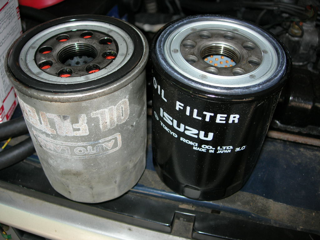 Finding an oil filter for the 4JB1-T engine was a bit of a hassle. Apparently, older versions of this engine used a filter identical to the one used on the Isuzu C223T, the diesel available in the Trooper in the USA. My engine, however, required a different filter with rather strange specifications. The center hole is 26mm wide, making it difficult to match.
I found a page which listed a few different part numbers (go to the 'workshop' link and select 'part numbers') but none of them crossed over to any North American manufacturers. A 4x4wire member then found this page, which again lists a few different options plus an OEM number. Here is the 4x4wire thread discussing this.
I called my nearest Isuzu industrial dealer and was able to order filters based on this number. Apparently, no other Isuzu filters in the USA will fit, and there are no known aftermarket crossover parts available, so this is the only filter that will work (save for parts ordered from overseas).
As an aside, it is not a dual-stage filter like the one I removed from the engine. This means I will need to change it more often than the dual-stage interval of 7500 miles, but that's fine with me. The only other problem is that they cost $20 each!
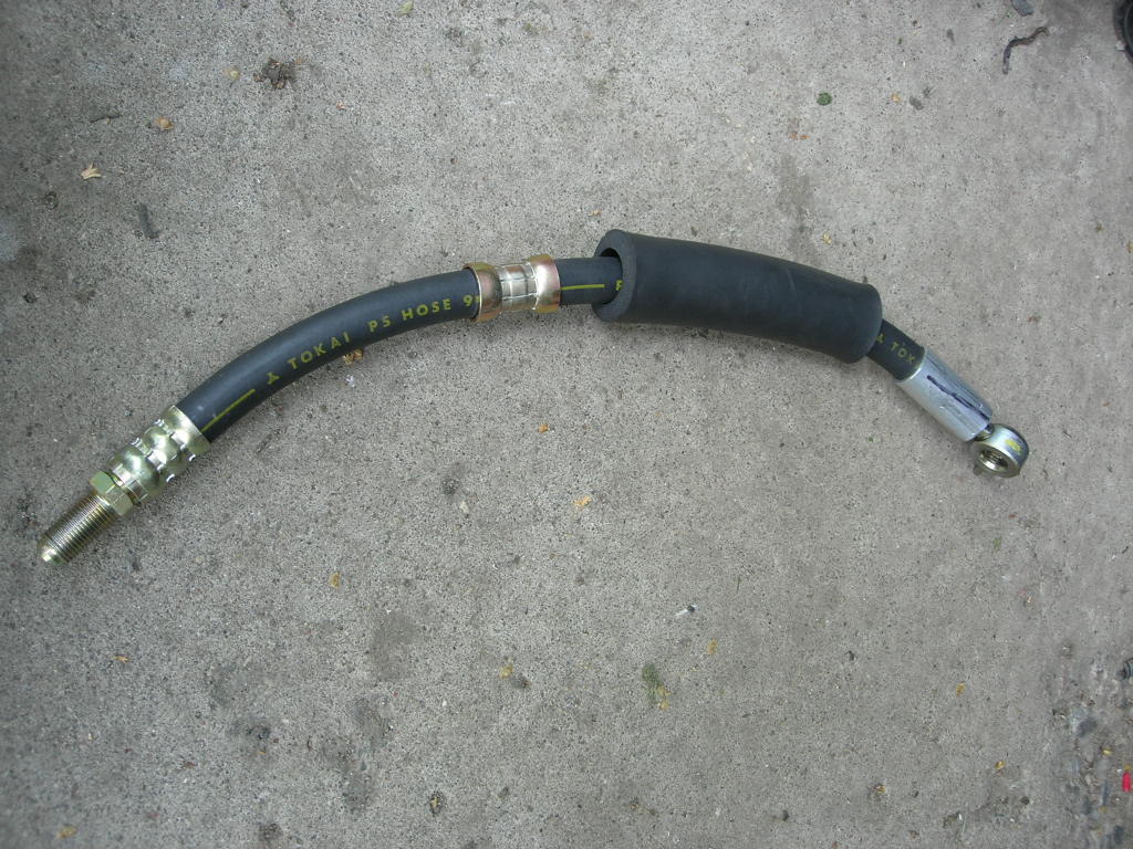
Power steering revisited


Due to the custom pressure hose breaking at the pump fitting (due to a hose defect), I needed to re-work the power steering system a bit. The complicated pressure hose routing described earlier was eliminated in favor of a much simpler design. Instead of running to a hardline connected to the steering sector, the hose now runs directly from the pump to the sector.
The connection at the pump is a stock Trooper part. This one came with my diesel engine, but it is identical to the fitting on the 4-cyl. gas engine pressure hose (except for the pin on the side of the diesel connector - this is not necessary and I considered cutting it off). The hydraulic shop cut the hardline off the fitting and brazed on a standard threaded flare connector. This creates an adaptor fitting which can be connected to the rubber pressure hose itself.
The steering sector fitting is another stock Isuzu part, this one having been cut off the old power steering return line, which ran from the reservior to the steering sector and threaded right in. The pressure and return ports are the same thread size, so the fitting was cut off from the old hose and again brazed to a standard fitting, creating an adaptor fitting at the other end.
The hose itself is a rubber pressure hose with identical fittings on each end which allow the two Isuzu adaptors to be threaded on. This way, if the hose ever fails or deteriorates, I can just have a new center section made and re-use the fittings.
The upper right photo shows (most of) the new hose. The upper left photo shows it installed, with another short section of hose added on at the sector end to account for my measuring mistake. Next time, I will be more careful and only need to buy one section of hose!
Sunday, June 04, 2006
engine bay shot
 And here is a shot of the current state of the engine bay. Messy, but starting to come together...
air filter
 Not much fabrication here - the stock diesel Trooper airbox, filter etc. all bolt in without hassles. The flexible rubber intake hose fits with a little trimming. I did have to cut a small notch in the airbox cover which allowed it to rotate toward the engine a few degrees in order to fit the hose correctly.
radiator and hoses

 The radiator used is a unit from a 1986 diesel Trooper. The hose inlet/outlet are on opposite sides of the radiator (as compared to the radiator from the gas Trooper); the core is also thicker and the tanks are larger, it's much more robust overall. The radiator and shroud are bolt-in items, no modifications needed to mount to the chassis.
The upper radiator hose, shown above right, is also from a diesel Trooper. It required minor trimming to fit.
The lower hose (above left, shown from underneath, with the near end being the engine end) was problematic. The engine-side inlet is larger than the outlet on the radiator and is located slightly to the side of the outlet. I tried to find a hose that had the curvature I needed which also changed diameter at some point, but I was unsuccessful (not to mention annoying to the fellows at the parts counter). Additionally, the distance is too short to use any sort of universal flexible hose.
I decided to have the radiator modified and have the outlet enlarged to match the inlet tube on the engine. With this done, I found that Gates hose #22364 has a curved section that fits perfectly (after removing a 90-degree bend at one end). According to the Gates site, this hose fits a 1998-2001 Ford Ranger or Mazda B2500 pickup. I am not sure which hose it is, or which engine it fits, but these trucks are common so I don't anticipate any problems finding spares in the future.
power steering continued


These photos show the pump connections and pressure line routing for the power steering system. The new bracket and hardline are visible in the photo on the right.
power steering


The power steering system was completed using a custom flexible pressure hose, a fabricated bracket to hold it in place and a new hardline to connect the pressure hose to the steering sector.
The pressure hose uses the pump end that came with the engine (although this is the same fitting the gas Trooper hose uses, just not as long and full of curves) and the opposite end is the same as the gas Trooper hose as well. I believe this hose is actually a Rodeo hose which has been modified at the pump end, as the Rodeo hose pump fitting looks to be correct at first glance but is actually different in inner diameter and will not work with the Trooper pump. Thanks to Jerry Lemond for the hydraulic fabrication work and consultation on this stage of the project. As far as I can tell, the diesel and gas power steering pumps are identical save for the pulley.
The pressure hose then travels down along the side of the radiator and is secured by a bracket I fabricated. The connection is the same as the stock gas Trooper and uses the top half of the factory bracket to retain the hose. The lower half of the bracket is a piece of angle iron. The bracket attaches to the frame on top of the bracket that holds the power steering hardlines that run along the frame, below the radiator.
The new hardline was made from a length of 3/16" brake line (I believe that's the dimension - I matched the old hardline I removed from the truck) which was bent to connect the pressure hose to the sector. The fittings on the ends were taken from the old hardline and re-used. It was time-consuming to get the bends just right, as the line is fairly short and has to be pretty much perfect or the threads won't start correctly in the sector or at the pressure hose.
The 1986 diesel Trooper uses the fluid return line as the cooler and this line is looped from the reservior to the sector, running along the frame below the radiator. The gas Trooper cools the fluid using the pressure line, as the pump is on the passenger side of the engine bay and the pressure line has to run across to the opposite side anyway. I removed the old pressure line and so was left without a cooler line. I decided to install the diesel cooler line, as it was the easiest solution (it bolts right in, no modifications needed).
The reservior was connected to the pump using a length of silicone heater hose, which is oil-resistant. The return line (below the radiator, as factory for diesel Troopers) is connected to a length of transmission oil cooler line which runs from the hardline up to the reservior.
If I had to do this again, I would modify the pressure hose end to match the return line from the gas Trooper, as the gas design reservior-to-sector hose screws into the sector. This way, I would be able to eliminate the bracket and hardline I fabricated and attach the new pressure hose directly to the steering sector. This would have saved hours of work.